Tag Archive for: FRP Pipe

FRP vs Aluminum: A Snapshot Comparison of Two Materials

frp vs aluminumFRP and Fiberglass

Fiberglass is ubiquitous in a wide range of industries from pulp and paper, wastewater, desalination, and power generation to mining and mineral extraction, marine, petrochemical and chemical processing. There are significant differences with respect to mechanical properties when comparing fiberglass or fiber reinforced polymers (FRP) with metals such as steel or aluminum. Fiberglass is anisotropic, that is, they posses mechanical properties only in the direction of the applied load. In other words, their best mechanical properties are in the direction of the fiber placement. Conversely, steel and aluminum are isotropic, giving them uniform properties in all directions, independent of the applied load.

Fiberglass has exceptional inherent dimensional stability potential due to its unique formulations. Because composites are customizable, they can be designed to maximize the benefits of structural properties. Furthermore, fiberglass materials are often selected by engineers for applications requiring stringent dimensional stability under a variety of extreme conditions. Good dimensional stability or structure, and other properties such as lightweight, strength, toughness, damage tolerance, fatigue and fracture resistance, notch sensitivity, and general durability, make fiberglass desirable for many applications. Moreover, the inherent corrosion resistant characteristic of fiberglass makes it a cost-­‐effective, strong, lightweight solution for corrosion resistant equipment applications in a multitude of industries including chemical processing, wastewater management, and oil and gas.

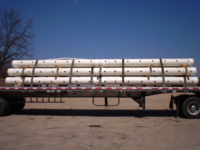
When comparing strength of materials of equivalent thicknesses and sizes, fiberglass will weigh one seventh as much as steel and half as much as aluminum. There are other very distinct advantages to having specific strength. For example, lightweight properties are important when considering the cost and ease of installation, especially for pipe and tank. FRP has another inherent edge over other products when equipment must be mounted on uneven services, existing structures, such as scrubbers, and on mezzanines or rooftops. Having lightweight properties also works well for specialty applications such as tank trailers.

Aluminum

Aluminum is an abundant element in the Earth’s crust that is widely used throughout the world in a broad range of applications, almost always as an alloy for construction purposes. Its unique combination of properties makes aluminum one of the most versatile engineering and construction materials. Aluminum is refined through the Bayer Process from aluminum ore or bauxite and once refined can be easily formed, machined and cast.

Some key properties include lightweight (about 1/3 mass, of equivalent volumes of steel, copper), excellent thermal and electrical conductivity, highly reflective to radiant energy, highly corrosion resistant to air and water (including sea water), and it’s highly workable into almost any structural shape. Corrosion resistance is a crucial property that can’t be overlooked; when aluminum is exposed to atmospheric conditions a thin oxide layer forms and protects the metal from further oxidation—this makes aluminum attractive as long-­‐term viable solution for many applications. This coating or layer provides protection and allows aluminum to often be used without any type of coating or paint.

One of the most important components of aluminum’s corrosion resistance is that the aluminum oxide layer formed is impermeable, adheres well to the parent material, and if damaged the oxide layer can repair itself immediately, generally speaking the layer is stable in a pH range of 4-­‐9.

So how does aluminum react in chemical environments? Generally speaking aluminum has good resistance to many organic compounds and some moderately alkaline water solutions, and most inorganic salts. As such aluminum materials are often used in the production and storage of many chemicals. One point of interest, for this article involves the pH range. A low or high pH range (below 4 or above 9) can lead to the oxide layer dissolving and corrosive attack. For example inorganic acids, strong alkaline solutions, and heavy metal salts are extremely corrosive to aluminum.

A key takeaway from this article, with respect to aluminum, is that there are important corrosion resistant limitations, and or chemical resistance limitations. For example, aluminum is susceptible to pitting corrosion, this typically happens in the presence of an electrolyte in dissolved salts, usually chlorides. Fiberglass is not susceptible to pitting corrosion in the presence of chlorides.

As with any material, limitations of one create opportunities for others. For example, aluminum is not compatible with, and should not be used in applications that included hydrochloric acid or sulfuric acid. Similarly it is not recommended for service environments that contain chlorine, sodium hypochlorite and ferric chloride, thus making it not an ideal candidate for some wastewater treatment applications.
Conversely, fiberglass has excellent corrosion properties for organic and inorganic compounds, alkaline and acidic environments including chemical resistance to the chemicals mentioned above. Fiberglass is now commonly used in wastewater treatment and or chemical processing applications using sodium hypochlorite, chlorine and or ferric chloride.

Similarly, there are structural property limits such as fatigue strength or fatigue limit that must be considered by engineers. For example, aluminum has no defined fatigue limit (fatigue failure eventually occurs) engineers must assess loads and designs for a fixed life. In contrast, when designed properly, fiberglass does not

creep, and has outstanding dimensional stability; fiberglass is strong lightweight and durable and in many cases a cost-­‐effective solution.

To summarize, fiberglass has a higher-­‐strength to weight ratio and better corrosion resistance in a wide range of chemical applications, when compared to aluminum. When working with fiberglass corrosion resistance can be enhanced by modifying the corrosion barrier to design specifications. Both offer design flexibility and some degree cost-­‐effectiveness with respect to reduced maintenance and long life cycles. An important structural difference is that fiberglass is anisotropic, while aluminum is isotropic. Both are limited by manufacturing processes and design.

Fiberglass Pipes and Fittings for a Chlorine Processing Plant

fiberglass pipes and fittings
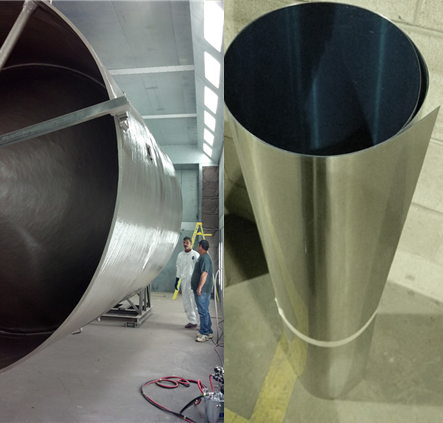
When an international client came to us needing pipes and fittings for a chlorine processing facility, we knew could help them.

In addition to intimate knowledge of the international industry standards, we needed to come up with a solution that could handle wet chlorine gas and other corrosive materials. One of the advantages of working with FRP is that it can be formulated to be extremely corrosion resistant. This capability made FRP the ideal material for meeting this customers’ needs.

To see how we integrated corrosion resistant piping with our customers existing plant infrastructure, download the full case study by clicking the button below:  

Uses of Fiberglass Pipe and Large Diameter Fiberglass Pipe

Applications and Key Benefits

uses of fiberglass pipe
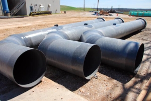
Since the mid to late 1980’s underground large-diameter composite piping has continued to grow in applications and usage. Technological advancements in the filament winding process, corrosion resistance, education and outreach, and strong market forces have contributed to the popularity of fiberglass pipe. Definitions of what constitutes large-diameter pipes can vary, but generally speaking they range from 12” to 14’ in diameter. 

Composite, or fiberglass pipe, has been utilized in a wide range of industries such as power generation, petrochemical and desalination.  Fiberglass pipe is corrosion resistant, has a life cycle that often exceeds 30 years, and has become increasingly more desirable as an alternative to steel, other metal alloys, ductile iron, and concrete.  According to an article published in 2008, titled “Large Diameter Pipe: Lasting Function in a World of Growth” more than 60,000 km (37,280 miles) of composite large diameter pipe are in operation around the world. 

Although fiberglass was once viewed as specialty product, for its ability to withstand an attack from sulphuric acid, it has now become a standard material, if not the standard in major market segments for a variety of reasons.  For example, fiberglass has been employed in drinking water projects, irrigation systems for agriculture, feed lines and penstock for hydroelectric power plants, power plant cooling water systems, gravity and pressure sanitary sewers systems, and pipeline rehabilitation “slip liners”.  Over the past two decades fiberglass has begun to transcend it’s early stereotypes as a one-trick pony (e.g. corrosion resistance) and has demonstrated its value as a cost-effective material, offering a plethora of end-user benefits.

Chief among the reasons for fiberglass increased usage and popularity are key benefits such as high strength-to-weight ratio, dimensional stability, good mechanical properties, ease of installation, reduced installation costs, reduced maintenance cost, and overall durability in extreme conditions. Similarly, another advantage of fiberglass pipe is it has a smoother inner surface when compared to traditional construction materials.  This attribute, smooth internal bore, resists scale-deposits and can create greater flow of service liquid over the life of the project.

When designing an underground large diameter pipe system many considerations need to be taken into account; local soil conditions, depth of water table, burial loads, live loads, deflection due to burial stress and operating temperatures—just to name a few.   Similarly, an American Water Works Association manual, Fiberglass Pipe Manual, also known as M45, provides equations that take into account factors such as fluid velocity and fluid pressure, head loss due to turbulent flow, water hammer, buckling pressure, and surge pressure.  Designing a proper underground piping system is a complex process that involves extensive calculations—product design should always be by qualified engineers. 

Pipe Support Systems

In general terms, industrial piping systems refer to a series of pipes used to transport materials from one location to another and also encompass pipe support systems.  A pipe support is a device or component designed to carry the weight of the pipe, any in-line equipment and the material in the pipe over a defined span.

In specific terms, the four main functions of a pipe support system is to guide, anchor, absorb shock, and support a specified load.  In addition, depending on the operating conditions (i.e. high or low temperatures) pipe support systems may contain insulation materials.

Four Main Functions of Pipe Support Systems

  • Guide
  • Anchor
  • Absorb Shock
  • Support a Specified Load

Types of Pipe Supports

  • Pipe Guide—directs and controls the motion of a defined span of pipe
  • Pipe Anchor—rigid support that restricts movement
  • Shock Absorber—absorbs or dissipates energy from the piping system

*Pipe supports can be designed for vertical, axial and/or lateral loading combinations.

Pipe System Design

The overall design configurations of a pipe support system will be determined by many factors such as loading, temperature, vacuum and other operating conditions. Although there are some basic guidelines used when designing FRP systems it is critical to note that each system is unique and must be treated as such. Thus, a detailed custom design is a crucial step when building a precision FRP pipe support system.

There are many considerations when designing a pipe systems and pipe support system; design temperature, design stresses (i.e. tension), design pressure, material densities,  thermal expansion, pressure expansion, modulus of elasticity, and thermal conductivity—just to name a few.

Pipe System Materials

Pipe support systems are generally made of FRP, structural steel, carbon steel, stainless steel, galvanized steel, aluminum, or ductile iron. FRP pipe supports have many unique  advantages over metal alloys.  For example, FRP can be formulated to be corrosion and abrasion resistant.

Other key FRP benefits include high strength-to-weight ratio, ease of installation, and dimensional stability (non-isotropic). Furthermore, FRP are well known for their long life cycles, reduced maintenance and their ability to withstand and perform exceptionally in extreme conditions. Moreover, FRP pipe supports have been utilized around the world in heavy industrial applications from pulp and paper and chemical processing to power generation—FRP are cost-effective construction materials.

We have over 50 years of fiberglass experience.  Leverage our key strengths; expert design intelligence, capacity, unmatched precision capabilities and exceptional field services.  We design, engineer and manufacture a wide range of custom FRP products including pipe supports.

FRP Corrosion Control: Education Can Improve Opportunities

frp corrosion
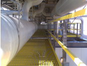
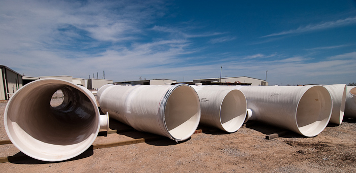
If you’ve been paying attention to fiberglass trends you’d know that corrosion, a serious problem that pits and corrodes most metals and metal alloys, has created huge market opportunities for Fiber Reinforced Polymers (FRP) including pipe, duct, and tanks.  Despite the many opportunities FRP manufactures have seized over the years, some major obstacles still persist, chief among them is education—or getting the word out. 

According to a 2012 article published in Composite Technologies, titled “Industrial Corrosion Control: Huge Opportunities,” lack of awareness or understanding of FRP benefits is ubiquitous among engineers.  There are a handful of other agents at work which have hindered FRP gaining traction in some industries.  Among them are a general unfamiliarity with FRP products; engineers are unsure of what resins or glass to select, reluctance to try a new material, thermal performance, the inability to distinguish good manufactures from bad, engineering departments at higher-education institutes, and economic paradigms.

Another commonly sighted impediment to FRP growth is new technological advancements and the uncertainties that they bring.  According to a 2009 study, released by the World Corrosion Organization, one such example is evident when considering carbon sequestration technology. Specifically, regarding large-scale underground storage of carbon dioxide, (generated from power plant exhaust gases), where nearly 40 pilot sites have been proposed, 10 of which are in the U.S. 

The report points out that the integrity of downhole tubing and cementing is strongly endangered by CO2 corrosion due to much more severe environmental conditions than normally encountered in traditional oil and gas production.   FRP are viewed by many as a cost-effective choice in instances like this because of their known abilities to withstand stringent, corrosive environments and demonstrate long life cycles with lower maintenance costs, but it will be up to manufactures and suppliers of FRP materials to make the case for composites and help educate and assist engineers.

More research is currently underway examining the environmental conditions and stresses that the material will be exposed to.  The many unknowns associated with Carbon and Capture Storage (CCS) technologies will need to be reviewed thoroughly—unknown concentrations of impurities such as oxygen, carbon monoxide (CO), and sulfur-containing gases like sulfur dioxide (SO2) or hydrogen sulfide (H2S) that are inevitably present in exhaust gases and are expected to be corrosive.  FRP are seen as a potential material solution in this for piping and other construction materials under such conditions.

Geothermal power production is another example where big opportunities for FRP exist with increased education and outreach.  In the geothermal industry, corrosion of plant equipment and structures within and around geothermal power generation facilities can be a major problem.  Issues with corrosion primarily arise due to the presence of salts, hydrogen sulfide (H2S), and silicates in the geothermal water, which cause localized corrosion and scale formation in wells and casings and power generating equipment. 

In both CCS and geothermal, technological advances have created new opportunities for FRP.   Many experts within each of these industries view FRP as a potential material solution for a variety of applications, but to overcome skepticism and uncertainty, education outreach efforts will need to be increased. Economic paradigms have already begun to shift in the past five to seven years, as the price of  metals have steadily rose allowing FRP to compete head to head against stainless steel and other alloys.  The bottom line is that as education regarding FRP continues so will the opportunities. 

For more information on our FRP and its uses, please visit us at http://www.beetlecomposites.com

FRP Pipe Testing using a Vacuum

Have you ever wondered what would happen to a 26″ diameter pipe in a vacuum? Well, we have and because we’re always looking for ways to make our products better, we found out.

We performed vacuum testing on a 26″ diameter pipe to study the effects of fiberglass pipe when subjected to a vacuum condition. The test performed was in accordance with ASTM D2924 and allowed us to determine the vacuum required to cause failure as well as the ultimate failure for analysis. With some outside of the box thinking our engineering was able to set up the test so that the inside of the pipe could be seen throughout the test. What was going on inside the pipe when exposed to a vacuum condition was one of those interesting things that we could not visualize, so we found a way to watch it. The results of the testing provided us important data about our product that can be utilized by our engineering and design personnel and contribute to the continuous product improvement at Beetle Plastics.

The ASTM Test D2924 was conducted on a 26” Diameter Pipe to determine the vacuum required to cause failure mode, and ultimate failure for analysis. The results of the test showed the failure mode was cracking along the lateral line of the inside of the pipe, however the outer wall of the pipe had no visible damage.

FRP Pipe Industry Leaders

frpBeetle Plastics has a rich history of strength in engineering and technical support. Overtime, our image in the industry has changed, as is so often the case for long lived companies. However, since Midwest Towers purchased Beetle a concerted effort has been made to rebuild our engineering base and great strides have been made to be an active player in the technical aspects of the industry.

We now have 3 individuals, Keith Sherman (Beetle Engineering and Design), Bill Daugherty (Beetle Engineering Design and Fabrication), and Tom Toth (Senior Structural Engineer @ MTI) that are directly involved in national committees developing standards and certifications. One particular committee that is of importance to end users, engineering firms, and manufacturers is the ASME Committee on Nonmetallic Pressure Piping Systems. This committee is comprised of respected engineering minds in the fiberglass industry and Tom, Keith, and Bill are active members.

Of particular interest is the development of a new FRP piping standard. The new standard will include design, material, manufacturing, fabrication, installation, installation, inspection, testing, and examination requirements and will affect nearly all users of FRP piping systems. Since this standard will be applied to the pipe, along with bolting, gaskets, valves, fittings, and almost all other components related to FRP piping, we are very excited that three of our own people will have a hand in shaping this industry standard.

We are excited to again be at the forefront of the technical side of the industry and look forward to providing our readers with the newest in industry updates.

The Large Diameter Composite Pipe Market Continues to Grow

Fiber reinforced polymer (FRP) is our passion here at Beetle, which is why we were very pleased to see a recent article published by Reinforced Plastics.com. “Large diameter composite pipe is gaining market share at the expense of pipe made with commodity materials, in general-purpose as well as specialty applications, ” Ben E Bogner in the article “Large Diameter Composite Pipe: Lasting Function in a World of Growth.” It’s no secret that FRP pipe isn’t the most glamorous of FRP applications, but functionality and durability have allowed the large diameter composite pipe industry to gain in strength as pipe made with iron and concrete lose market shares.

When we talk about large diameter pipe, we’re generally referring to, “pipe that is at least 12 inch in diameter. At the higher end, the sector includes composite pipe in diameters as large as 14 feet.” This sort of pipe is generally used for a number of applications, but the most common, according to the article, are:

  • drinking water projects such as raw water supply lines for potable water systems;
  • irrigation systems for agriculture;
  • feed lines and penstock for hydroelectric power plants;
  • circulation for cooling water systems, primarily for power plants;
  • sanitary sewer projects for pressure as well as gravity sewer systems, and
  • pipeline rehabilitation as ‘slip liners.’

There are a number of features that have contributed to the increased market share controlled by composite large pipes. One of the most attractive features of FRP pipe is that is it resistant to corrosion, even the corrosion you see with sulphuric acid. Composites are also a cost effective  alternative to other kinds of raw materials like pig iron and steel. Even though all kinds of raw materials costs have been steadily creeping upward, the cost of composites hasn’t increased nearly as much.

“Another reason for the increased market share is the fact that FRP pipes for the last 30 years have proven to be a reliable alternative. More than 60 000 km (37 280 miles) of composite large diameter pipe are in operation worldwide to prove that the material will perform long-term as predicted.”

To read the full article, click here.

How to Properly Bury Fiberglass Piping

Beetle Plastics has developed a series of specifications that pertain to buried flexible fiberglass piping where the fiberglass pipe, trench walls, and bedding material work together to form a complete pipe support system. This post outlines the sections covered in our engineering document available for download.

The elements of this system can best be defined by considering a section of buried flexible pipe and the loads acting on it. These loads, the dead load (backfill) and the live loads (vehicle traffic), act downward on the pipe, tending to deflect it into an oval shape. If the bedding material at the sides of the pipe is compacted sufficiently, it will resist the pipe movement and minimize the deflection and ovalization to an acceptable amount. For this reason, the construction of the trench and selection of bedding materials must be closely controlled.

These specifications cover the burial techniques required for the installation of fiberglass pipe under most conditions.

SECTION I: Fiberglass Pipe Storage and Handling

When storing fiberglass pipe directly on the ground, select a flat area free of rocks and other debris that could damage the pipe. Also, when preparing the ends for joining (butt wrap or tapered bell and spigot joints), do not roll the pipe over rocks, debris, or uneven ground that does not fully support the pipe.

SECTION II: Trench Excavation and Preparation

The actual depth of the trench is determined by the final grade, plus the depth required for the initial (bottom) layer of bedding material. The soil conditions and bedding materials being used will determine this additional depth.

Nominal trench widths are listed in the engineering guide available for download.

SECTION III: Bedding and Backfilling

The trench bottom is the first element of the pipe support system. There are many things to consider when building the bedding including pipe diameter, pipe type, soil type and density, and water table.

Schematics and details are contained in the fiberglass pipe engineering document.

SECTION IV: Concrete Structure

Where the fiberglass piping goes through or passes under a concrete structure, precautions must be taken to prevent excessive strain on the pipe due to the differential settling between the structure and the pipe. There are several methods discussed in the engineering document for compensating for settling without straining the fiberglass pipe.

Contact us today about your fiberglass pipe and tank requirements.

Fiberglass Pipe Thermal Expansion and Contraction

frp material properties, frp pipe

FRP Pipe Properties: Thermal Expansion and Contraction

Beetle Plastics fiberglass pipe is filament wound and, therefore, has different thermal expansion in the hoop and axial direction. In the hoop direction, the thermal expansion is about the same as steel. However, in the axial direction, the thermal expansion of the fiberglass pipe is about twice that of steel.

The relatively low modulus of elasticity of the fiberglass pipe is an advantage which should be considered in the design of a piping system. Since thermal forces are smaller, restraining equipment (guides, anchors, etc.) need not be as strong or heavy as for steel piping. There is some growth due to end load from pressure in the piping system; but experience has shown that this length change does not need to be considered in designing a fiberglass piping system. FRP composite piping systems can handle thermal shocks between maximum rated operating temperatures and -40°F, unless the pipe joints are mechanical joint style.

To determine the effects of expansion and contraction within a piping system, it is necessary to know:

  1. The design temperature conditions.
  2. The type and size of pipe.
  3. The layout of the system including dimensions and the thermal movements, if any, of the terminal
  4. points.
  5. The limitations on end reactions at terminal points as established by equipment manufacturers.
  6. The temperature changes for expansion are calculated by subtracting the installation temperature (temperature at time of final tie in) from the maximum design temperature.

Temperature changesfor contraction are calculated by subtracting the minimum design temperature from the installation temperature. Expansion and contractions of above ground fiberglass pipe may be handled by several different methods.

Four methods are:

  1. Direction Changes
  2. Anchors and Guides
  3. Mechanical Expansion Joints
  4. Expansion Loops

Guides, Expansion Loops, and Mechanical Expansion Joints are installed in straight pipelines which are anchored at both ends. The experience of users of FRP composite piping systems has shown that if directional changes cannot be used to accommodate thermal expansion and contraction, then the guide spacing design approach is usually the most economical method.

Operating experience with piping systems indicates that it is a good practice to anchor long straight pipe runs of above group piping at approximately 300-foot intervals. These anchors prevent pipe movement due to vibration, water hammer, etc.. Also, an anchor is used wherever a pipe size change occurs. When joining FRP composite piping to other piping systems, the adjoining system MUST be securely anchored to prevent the transfer of thermal end loads.

Contact us today and we can arrange a test installation in your plant comparing Beetle Plastics abrasion resistant pipe with your current piping and duct materials.

Tag Archive for: FRP Pipe

Pipe Support Systems